Transforaminal Percutaneous Endoscopic Lumbar Discectomy Through a Transfacet Approach: Detailed Surgical Technique
Article information
Abstract
The percutaneous endoscopic lumbar discectomy (PELD) is a minimally invasive surgical approach described for the treatment of herniated lumbar disks. We aim to offer a brief anatomical review followed by a detailed and illustrated description of the transforaminal PELD technique using the Tom SHIDI endoscope and instrument set (MaxMoreSpine, Unterföhring, Germany).
The transforaminal PELD through a transforaminal approach using Tom SHIDI allows safe surgical treatment of most lumbar hernias thanks to the posterior entrance into Kambin's Triangle through a bony landmark allowing foraminoplasty to be performed using a manual drill. Careful surgical technique minimizes unforeseen complications and makes this a safe and viable alternative to conventional microdiscectomy.
INTRODUCTION
The percutaneous endoscopic lumbar discectomy (PELD) is a minimally invasive surgical approach described for the treatment of herniated lumbar disks. Recently, the refinement of the surgical technique aided by technological improvements in instruments, surgical tools and visualization equipment (high definition endoscopes) led to the dissemination of this approach in the 1990’s. Early publications described the adaptation and use of endoscopes developed for other surgical areas to perform the PELD, through either a transforaminal or translaminar approach to remove the herniated disk. Nowadays, there are new endoscopes and instruments developed specifically for PELD available to spine surgeons. We aim to carefully describe the transforaminal PELD technique using the Tom SHIDI endoscope and instrument set (MaxMoreSpine, Unterföhring, Germany).
1. Anatomy
The transforaminal PELD is performed through the Kambin triangle, formed by the superior plateau of the inferior vertebra (base, inferior limit), the superior articular facet (height, medial limit), and the nerve root (lateral limit) (Figure 1).
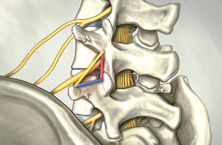
Anatomical limits of the Kambin Triangle: Superior plateau of the infetior vertebra (blue), superior articular facet (red) and the nerve root (yellow).
2. Indication and Limitations of the Approach
This technique can be used at all lumbar levels and the indications are the same as a standard microdiscetomy. Major limitations of this approach are high grade spondylolisthesis and a significantly narrow canal. Minor limitations, which can be overcome by an experienced surgeon but should, nonetheless, be assessed in a case-by-case basis, are sequestered hernias, cranially migrated hernias and L5S1 hernia with a high iliac crest relative to the affected level.
3. Surgical Technique
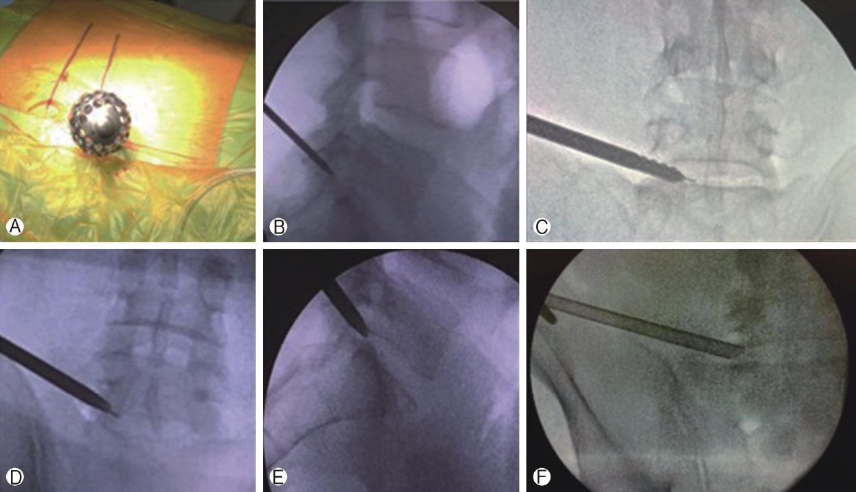
The patient is placed in prone position, similar to a standard microdiscectomy. Two support bolsters are placed under both sides of the thorax and a transverse support pad is used under the iliac crests to maintain lordosis and to avoid compression of the abdomen, which increases bleeding due to venous engorgement. Before prepping and draping the surgical area, the C-arm fluoroscopy, a surgical marker and a Kirschner’s wire (or K-wire) are used to determine and mark the relevant landmarks for the approach. The rotation and angulation of the C-arm must be carefully adjusted to align the superior and inferior plateaus of the level of the hernia (Figure 2).

Ⓐ: marking the midline. Ⓑ: L4’s inferior plateau and L5’s superior plateau, midline and the estimated path of the endoscope. Ⓒ: Marking the endoscope’s path for a right side, L5-S1 hernianote the iliac crest. Ⓓ: Anteroposterior fluoroscopy using the K-Wire to determine the midline, centering the wire on top of the spinous processes. Ⓔ: Estimated path of the endoscope for a left-side, L4-L5 hernia. Ⓕ Estimated path of the endoscope for a right side, L5-S1 hernia.
The landmarks that should be marked after adjusting the C-arm are:
1) The midline passing through the spinous processes of the vertebrae.
2) The iliac crest (manly when performing a L5-S1 PELD).
3) The inferior and superior plateaus of the superior and inferior vertebrae adjacent to the disk to be approached.
4) The endoscope’s path: it should transverse the cranial portion of the superior articular process of the inferior vertebra on the approached side to the midpoint of the superior plateau of the inferior vertebra. The path should be at an angle and not parallel to the adjacent plateaus. This angle should be between 20 and 30 degrees for L3-L4, 30 to 40 degrees for L4-L5, and 40 to 50 degrees for L5-S1. The smallest angle possible for this path, should be used in order to facilitate the discectomy. This angle may be wider according to the height of the iliac crest (specially for L5-S1 hernias) and to the patient’s lordosis.
5) After marking the path of the endoscope, the entry point must be ascertained. It is marked along the path of the endoscope, measuring the perpendicular distance from the previously marked midline. For levels L1-L2, L2-L3, and L3-L4 the distance is 8 cm. For L4-L5 it is 10 cm. For L5-S1 it is 12 cm. For patients with abundant dorsal adipose tissue, the entry point calculation should be 2 cm further away from the midline than the distances described above.
After prepping the skin in a standard fashion, the surgical drapes are placed. A collecting bag with a suction should also be placed to collect the excess irrigation. When available, the suction should be used with a filter to retains disk fragments that may be expelled with the irrigation. A local anesthetic block using 2% lidocaine is done at the entry point and an 18G spinal needle is advanced percutaneously toward the superior articular process, using anteroposterior fluoroscopy guidance.
The angle of the needle directly relates to the adipose tissue of the patient and varies between 15 and 50 degrees. The C-arm is alternated from the anteroposterior and the laterolateral exposures as the needle is advanced to reach the cranial portion of the superior articular process, avoiding any accidental injuries to vascular or visceral structures surrounding the lumbar spine.
Aiming the needle toward the superior articular process rather than the foramen itself provides extra protection to reach Kambin’s Triangle, specially at the L5-S1 level, where the foramen is usually smaller. When the superior articular process is reached 2% lidocaine is once again infused to block the periosteum.
A K-wire is then introduced and the needle, removed. From this moment on, the K-wire is used as the guide to advance the instruments, making sure that it is at the superior articular process at all times. If the wire is accidentally removed, the needle should be reintroduce following the same procedure as before. The inadvertent advance of the k-wire into the foramen may injure neural or vascular structures and should be avoided.
With the k-wire in place, a small skin incision (9 to 12 mm) is done using a number 11 blade. Then, two dilators, one 3 mm and the next 6.3 mm, are advanced through the thoracolumbar fascia and muscles. Stronger but gentle force is needed to reach the target.
After the dilator, the blunt tip TOM Shidi tool is used (Figure 3), the K-wire is removed, and the sharp tip TOM Shidi is introduced. Fluoroscopy is used to confirm the position of the sharp tip on the cranial portion of the superior articular process. The sharp edge crates an indirect entrance into the posterior portion of Kambin’s Triangle. The TOM Shidi tool set allows such a posterior entrance, protecting the nerve root.
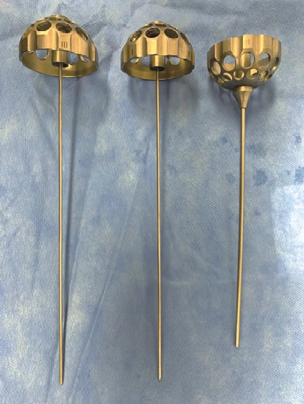
The TOM Shidi instruments set.
Using a surgical mallet, under anteroposterior radioscopy guidance, we advance the sharp tip TOM Shidi to 1 mm before reaching the medial interpedicular line to avoid any injuries by the sharp edge, if the spinal canal should be inadvertently violated. Therefore, we replace the sharp tip with the blunt tip and continue advancing safely beyond the interpedicular line, approximately 1 mm (Figure 4).
Ⓐ, Ⓑ: The TOM Shidi is inside the cranial portion of the superior articular process. Ⓒ: Followed by the sequential manual drills to enlarge the entrance created by the TOM Shidi. Ⓓ, Ⓔ: The dilator in its final position before introducing the endoscope’s jacket in an anteroposterior and laterolateral view. Ⓕ: The endoscope’s jacket in its final position in L5-S1.
The narrow space created by the TOM Shidi must be enlarged for the endoscope to enter. The blunt tip TOM Shidi is removed and the K-wire is reintroduced to guide manual dilating drills. Progressively larger drills (with 4, 6, 7, and 8 mm) are used in sequence. After the last drill, the initial dilator is reintroduced along with the endoscope’s jacket using the K-wire as guidance until 2/3 of its tapered edge are in the foramen, under anteroposterior radioscopy. The K-wire is removed, and the jacket is advanced 2mm using the surgical mallet into the opening in the superior articular facet to avoid movement of the jacket. The tapered edge of the jacket should lie towards the patient’s back.
The endoscope is finally introduced. The anatomical landmarks we are able to identify are: (1) the superior plateau of the inferior vertebra, (2) superior articular facet, and (3) the intervertebral disc. From this point of view, the emerging nerve root lies at 12 o’clock, between the disc and the exposed facet. If further removal of the superior articular process is needed, an endoscopic kerrison rongeur or high-speed drill can be used.
We start the discectomy using endoscopic grasping forceps and as it proceeds the epidural space becomes clearer and epidural adipose tissue is identified. Epidural fat should not be grasped to avoid unnecessary bleeding from epidural vessels. If bleeding does happen, an endoscopic bipolar can easily control it and should always be available and ready for use. After the discectomy, the nerve root can be seen.
The decompression can be considered satisfactory and the procedure, concluded according to three different parameters analyzed together: (1) the volume of disc removed compared to the herniated volume as demonstrated by the pre-operative magnetic resonance imaging (MRI); (2) free pulsation of epidural fat; and (3) visualization of the nerve root free of any compression (Figure 5).
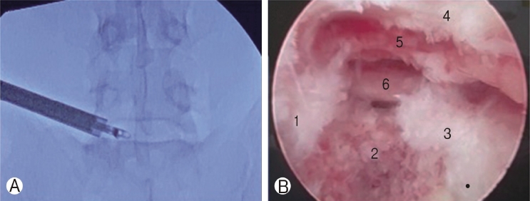
Ⓐ: Final position of the endoscope immediately above the iliac crest, with the grasping forceps introduced through the work channel of the endoscope to perform an L5-S1 discectomy. Ⓑ: Final endoscopic view after discectomy and decompression of S1 nerve root. Where the following structures can be seen: 1. inferior plateau of the L5 vertebra; 2. remaining disc; 3. superior plateau of the S1 vertebra; 4. superior articular facet of S1 vertebra; 5. epidural fat; 6. S1 emerging nerve root.
The endoscope and its jacket are removed together and the small skin incision is closed using intradermic suture (Figure 6). This procedure may be done under general anesthesia or sedation and local anesthesia. We usually prefer general anesthesia without motor blockade, which we consider to be more comfortable for our patients. The TOM Shidi instrument set allows a more posterior entrance into Kambin’s Triangle, through the superior facet of the inferior vertebra. This is a safe entry point for all levels and does not require somatosensory evoked potentials (SSEPs). The risk of nerve injury is close to null when all the anatomic landmarks are respected.
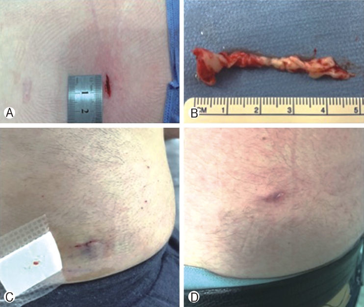
Ⓐ: Length of the incision. Ⓑ: The herniated disc that was removed. Ⓒ: The surgical wound after 24 hours. Ⓓ: Surgical wound at 7 days.
4. Post-operative Assessment
The patient can be safely discharged after 2 hours(if performed under sedation and local anesthesia) or 4 hours (for general anesthesia). Some mild to moderate lumbar pain and transient paresthesia of the corresponding dermatome is expected. A new MRI is not required before six to eight weeks after surgery (Figure 7, 8). If radiculopathy persists (not only lumbar pain) an earlier MRI should be considered.
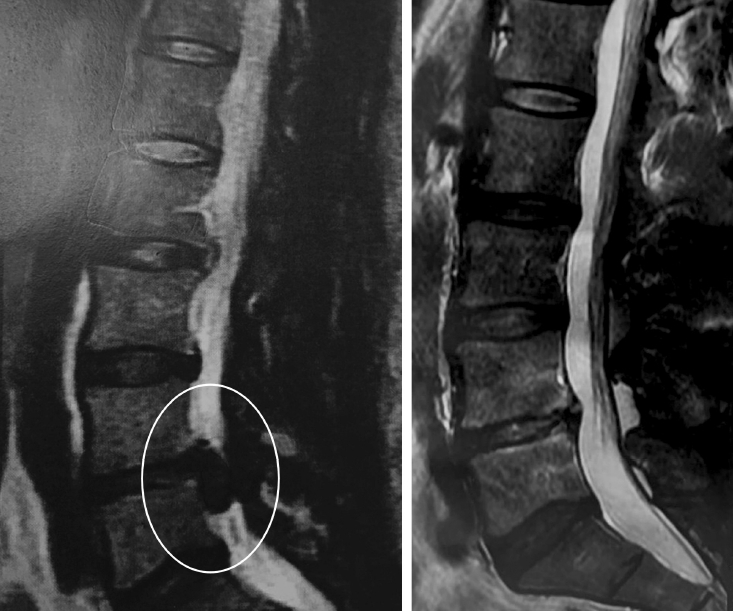
Pre- and post-operative T2-wheigted magnetic resonance images.
DISCUSSION
The Percutaneous Endoscopic Lumbar Discectomy can be safely performed through a transforaminal, an interlaminar, and a translaminar approach in most cases. There are different commercially available brands each with specific technical caveats [1,3]. The transforaminal approach through Kambin’s Triangle is usually done accessing the disc directly. The technique described here is an indirect access to the disc through Kambin’s Triangle, using the TOM Shidi endoscope and instrument set, developed by Thomas Hoogland, followed by manual drills which create an entrance in the superior articular facet [4]. The advantages of this technique are a safer route into the disc space, reducing the risk of injury to the emerging nerve root and, since high speed drills are seldom necessary, it also reduces costs.
The L5-S1 foramen is smaller and the emerging nerve root, more vertical reducing the area of Kambin’s Triangle. Therefore, this level is technically more challenging and there is a higher risk of injury to the nerve. Using a bony landmark (superior articular facet), rather than accessing the disc directly, makes this approach safer. Kambin’s Triangle is enlarged posteriorly, using different manual drills to dilate the entrance created by the TOM Shidi, allowing a safe outside-in discectomy [2].
CONCLUSION
The transforaminal PELD using the TOM Shidi instrument set allows safe surgical treatment of most lumbar hernias thanks to the posterior entrance into Kambin’s Triangle through a bony landmark, including L5-S1 hernias despite the iliac crest.
Careful surgical technique as described here minimizes unforeseen complications and makes this a safe and viable alternative to conventional microdiscectomy.
Notes
No potential conflict of interest relevant to this article.